

 Pearl Burgoff
1 min read
Webinar Review: GCs Learn How to Reduce time to Construction | Qnect
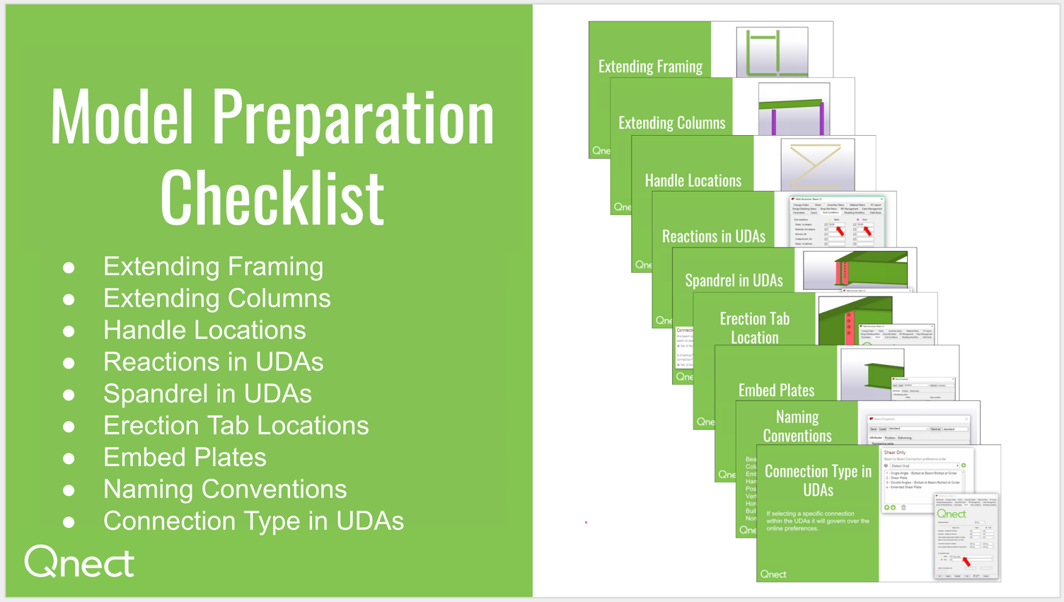
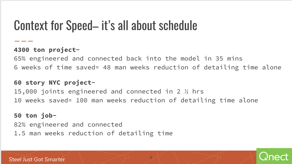
This special GC-focused webinar took place on November 20th, 2019. The webinar focuses on reducing time to construction for the general contractors....
You know that proper model preparation for fabrication can prevent unnecessary headaches and frustrations. Preparing the model right the first time, leads to a smooth project handoff and much more. So what are the secrets? How can I be sure that my model is ready for fabrication?
In this video, we explain best practices for model preparation.
We also have a few documents to support this video. So if you are unable to view, just download the "BIM Model Preparation" PDF and follow through the transcript, which has been adjusted for following along in the video or in the PDF. The transcript below follows the video.
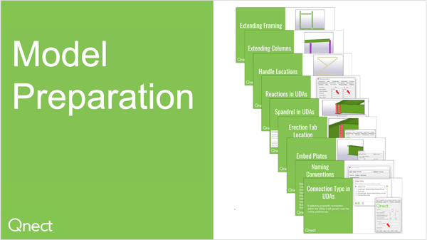
How to best prepare your model prior to running Qnect.
First, we will look at extending framing. We will be looking:
So as you can see on the top right hand side those are incorrect. On the bottom you'll see that those are correct. So when when extending a beam to beam we want to make sure the beam that is going to be supported is extended to a centerline of its supporting beam. 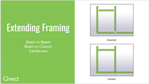 Same thing with a beam to column. We want to make sure that those beams are extended to the centerline of the column supporting them. And finally with cantilevers, as you can see in the bottom left-hand corner of the correct picture, you will notice that the beam vertical in this view is going to extend to the centerline of the cantilever beam. The cantilever beam will also extend out at least flush or past the beam that's framing into it.
Now let's look at column extensions. So we're going to extend columns to the top of Steel locations and if you have a splice or they go up both top of steel that's fine extended where you need to and then underside locatio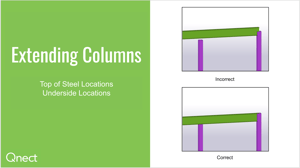 ns. As you can see on the top right, that is incorrect and on the bottom right those are correct. So you will make sure that you extend any columns up to the bottom of your steel and you will also extend any columns to the top of steel we don't want those sitting at a mid span of a beam.
There are some default extending tools in Tekla you can go type extend in your macros and you will find:
Next we will look at Start and End Handle locations. As many of you know start and end handle locations are very important when you're looking at a beam or a member on a shop joint. It always goes from left to right for a beam and that is your start and end handle. So as you can see in the incorrect view you'll notice all of the end handles are on the left hand side which is incorrect and in the correct picture you'll notice that all the start handles are on the left hand side. It's best practice to make sure when modeling that you have left to right approach in a plan north and also a bottom-to-top approach in a plan north. There's also a swap handles tool within Tekla.
Go to your macros and type in “swap.” You'll be able to go find that. And it is very important when swapping handles the UDA fields will remain and will not follow your handles. If you have something in a UDA field in a start handle location and you swap that because the handle was in the incorrect location that UDA field will not move; it will stay true to the start. Make sure when prepping your model you pay attention.
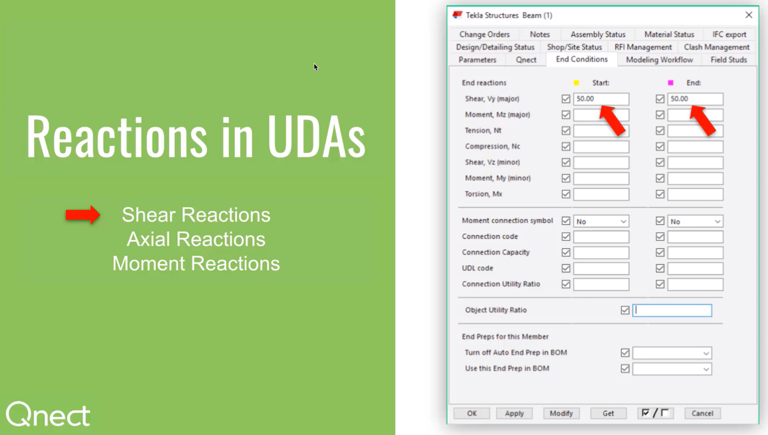
Next we will be looking at placing reactions in a UDA field. We'll be looking at:
When you need to place a reaction into the model you're going to go ahead and do that through the UDA fields. As you can see here 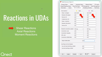 you're going to place the shear reactions. Then for axial we're actually going to locate two places. We're gonna put the load reaction in the tension as well as compression. Now for a moment you're gonna go ahead and put the reaction in the moment location but you also need to make sure that you check the box to “yes” where it says moment connections symbol. Because, if you have a reaction in there and that is still checked as “no” it will not actually try to complete a moment connection at that location. We will simply just move past.
Alright, next we're gonna look at spandrel beam locations and placing those in a UDA field. So what Qnect considers a spandrel beam is going to be something like a perimeter beam going from column to column or it could just be a perimeter beam where you're looking to place a full depth connection whether that is going to be an actual full depth shear plate or if that's going to be a maximum bolt row double angle connection. You also have the ability to say yes you do want a backside full depth stiffener. So as you can see in these three demonstrations you'll notice we have spandrel turned on in our UDA field as “yes” and then in our preferences we would also turn on “yes” for the full depth connection and then “yes” for the full depth backside stiffener. Okay, next we are going to look at erection tab locations.
We'll look at a near side a far side and then we actually have something coming out very soon which I think most of you will be pleased with so you know as we touched on before start and end handles are very important. This is another one of those reasons why so if you go to your start handle at a location like this and you go to the UDA field shear plate or single angle relative to beam and you go ahead and say “near” you are now going to see your connection on the near side. Then if you were to show that as “far” you will notice that that is on the far side. We've gotten a lot of questions about “is there a global approach to do this?” So as always we try to listen to our customers and provide as much as possible so coming very soon you'll be able to actually do that as a global approach so in your preferences you would set up how you want your locations to be placed and then you would simply just adjust the minimal locations required in the model.
Next we will be looking at embed plates. When we prepare a model for Qnect and we're gonna have an embed connection we actually have to place an embed at that location. We're not worried about studs on an embed - they can be there - but when we place this in here we want to make sure we have a viable, useable plate and if you you'll notice there's no plate on the top on the bottom 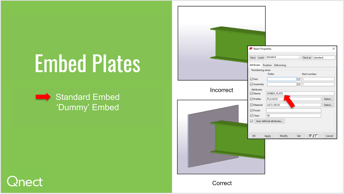 there is a plate; that is exactly what we need. There will be scenarios where you may get into an environment where you have to provide a dummy plate. So say you have two channels that are butted up together that's going to act as an actual embed. Well, what we would need at that point is a plate placed in there and you can put it in a filter for a specific class that gets turned off but when you go to select it for Qnect it's there for you to select the beam and that dummy plate to actually create that connection.
Alright, the next topic we'll look at is the naming conventions. We work with naming conventions. If you want us to look at certain members to be able to try and connect them with Qnect beams, columns, embeds, hangars, posts, so on and so forth actually have the exac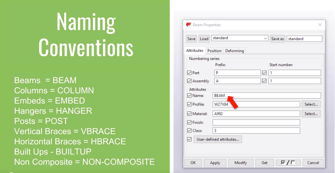 t name shown here that needs to be placed in the UDA field. For instance if you have a post then you want it to be called “post.” We also have the ability with non-composite beams to be able to distinguish a composite versus a non-composite. Depending on your load criteria you may want to do that so you would want to place non-composite in that name field. That's going to be a lot easier for you rather than going to the field stud location and placing studs in a UDA field at each member; that'd be a lot more time-consuming. Although, that is an option instead of the naming convention this is a much faster approach.
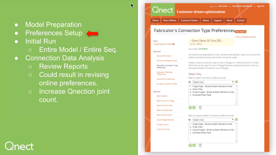
We have one final model preparation tool that has been added more recent and that is Connection Type Adjustability in a UDA. When we set up all of our preferences prior to running a model we use a hierarchy system here at Qnect. So if you have a beam to beam connection and you want to set that up to have a single angle bolted bolted connection we'll go ahead and put that first.
Now, if that connection cannot be met for the design criteria of that project and you would like it to then try to complete that connection with the shear plate that's how we would set it up as shown. Then it would go down the line if it couldn't do a shear plate to a double angle and if it couldn't do that it would go to an extended shear plate and then if it couldn't use any of those we simply would not place a connection in the model.
You do have the ability while prepping a model if you know that there will be certain specific connections outside of that global hierarchy approach that needs something else you can go ahead to your UDA field at your start and end handle locations yet again very important and you can manually select something like shear plate here. So at a location where shear plate would be tagged you actually would have the shear plate location connection at that location rather than trying the hierarchy system. Keep in mind if you do have a shear plate called out there and it cannot meet that connection it will no longer try any other connection that's in that hierarchy system. It will only try what is in the UDA field.
Access the Qnect app to enhance team collaboration and project efficiency. Sign in or create an account to manage communication and workflows with clarity and control.
1 min read
This special GC-focused webinar took place on November 20th, 2019. The webinar focuses on reducing time to construction for the general contractors....
1 min read
To be more specific this is a Preference Setting update that focuses on the Global Shear Plate and Single Angle Placement.
1 min read
This Post builds on an earlier Tech Tuesday post regarding Model Preparation and will be followed by a post on Analyzing the Data, which gives us...