

 Pearl Burgoff
1 min read
Connecting for Optimization by Jef Sharp in MSC | Qnect
"LAST MONTH, I wrote about how early connected models can help steel fabricators. This month, let’s expand the discussion to include the myriad...
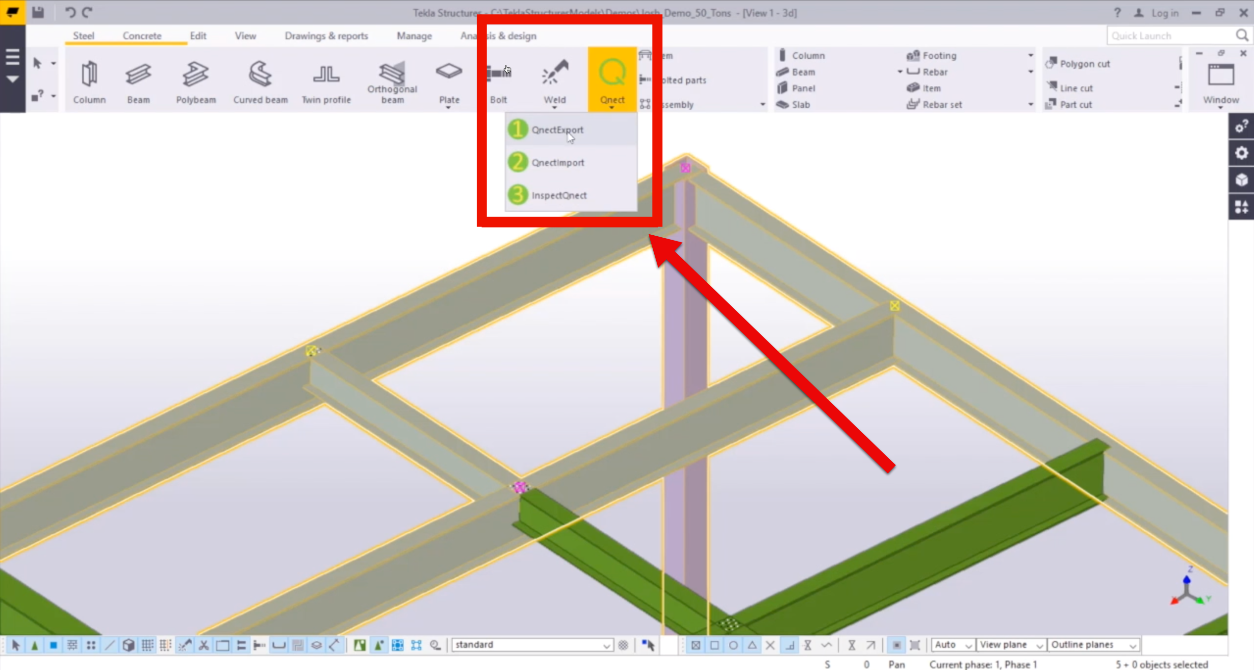
For this week's Tech Tuesday, we dive into Qnect’s Button 3.
Button 3 offers a number of productivity tools for QuickQnect users. You can use it to filter and show exactly the type of connections you want to inspect, then you can easily toggle through them for a visual check.
Button 3 also is where you will generate the 2D floorplan “Maps." These maps will show you which connections have been completed by Qnect and which are left over.
Keep an eye on Button 3, because we have great new productivity tools in the works for the next QuickQnect release!

Watch the short video now - it's about three and a half minutes.
Need to know more? Use the button below to schedule a meeting with us!

Welcome to this video my name is Islam and I will show you how to use button #3 in Qnect.
When you click button #3 you get InspectQnect window like this and on the left side here in this preview you can use it to filter your connections.
So you can choose whether you want beam to beam connections only beam to column flange also you can filter based on Qnect sessions.
Let's say I want to see beam to beam connections only. I'll apply filter. Click “hide” here this preview.
Here on this list you will see the session name, the main part ID, the secondary part ID and information about connection itself.
On here on those arrows you can switch between the connections - the next one or the previous one.
What Qnect actually does is that it will show you two views for the connection.
Here is a top view and a front view list like this and you can tile between them either horizontally or vertically.
In the connections here you see in the front view you can inspect your connection. Also, see if there is any drawing any issues and you can report issues if found.
It is very handy tool to go through all the connections and make sure that you inspect them all.
You can do is button #3 is to create a map drawing.
If you see here on the top there is a map and show no connect.
A map drawing will create a drawing for any particular view you have in the model and this drawing will have marks color-coded with a connection ID.
Let's say this part has two connections so it will have a green mark with a connection ID of each end.
If the part does not have any component it will show a red mark and you can see that in a drawing and it will help me to know where the locations of the parts which were not connected.
If you click map here and choose this floor and click create you can get also multiple floors we can select two floors and click create at the same time.
This is how the map drawn looks like.
As you see here this frame marks this green mark shows that this beam ends are both connected a start and the end. For this beam the two ends are not connected so the map can tell you where the beams which are not connected. That's it. Thank you for watching.
Access the Qnect app to enhance team collaboration and project efficiency. Sign in or create an account to manage communication and workflows with clarity and control.

1 min read
"LAST MONTH, I wrote about how early connected models can help steel fabricators. This month, let’s expand the discussion to include the myriad...
1 min read
To be more specific this is a Preference Setting update that focuses on the Global Shear Plate and Single Angle Placement.
1 min read
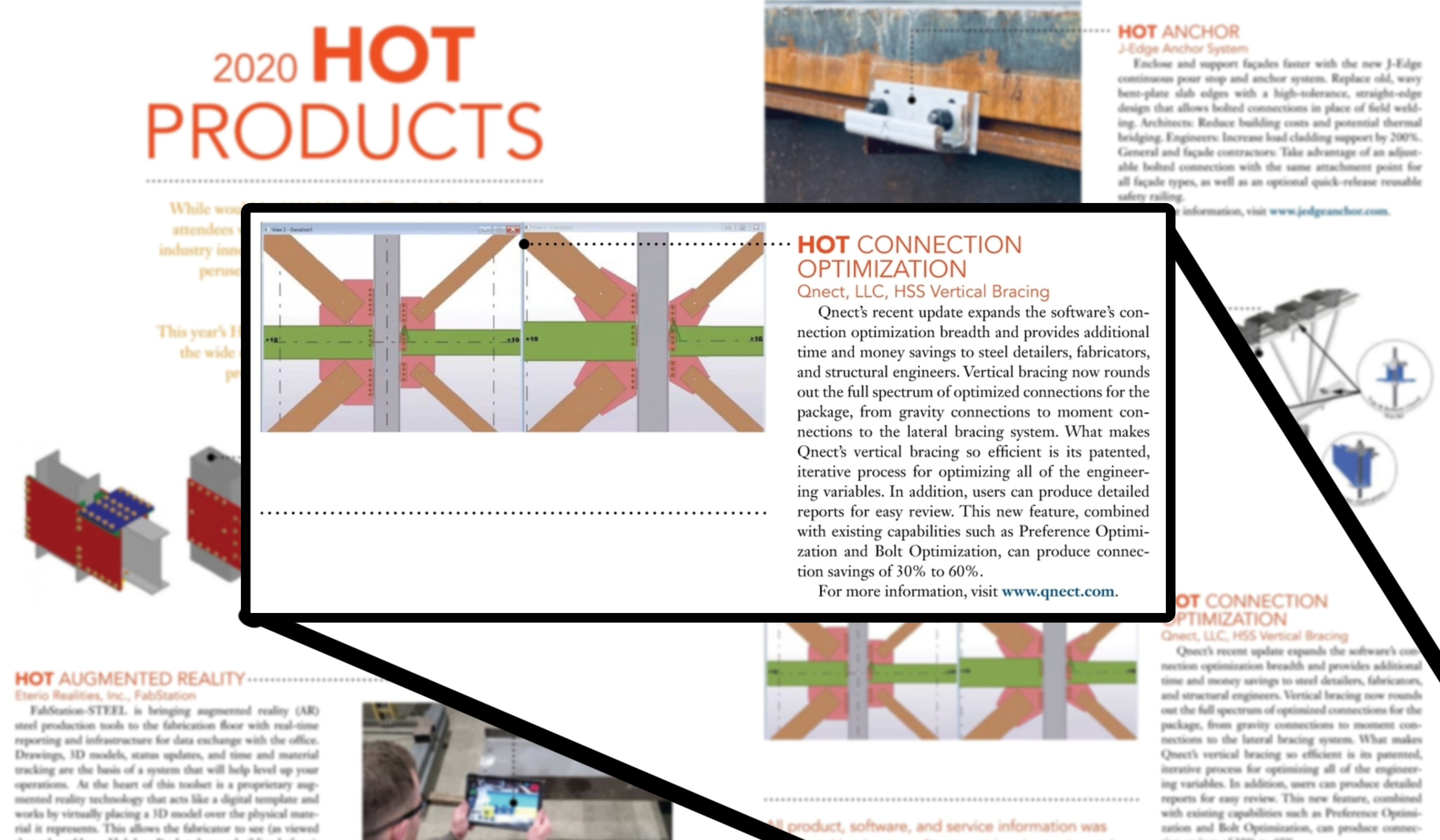
The Qnect development team took on a monumental task when they added Vertical Bracing Connections to the product roadmap. They were confident they...