Review
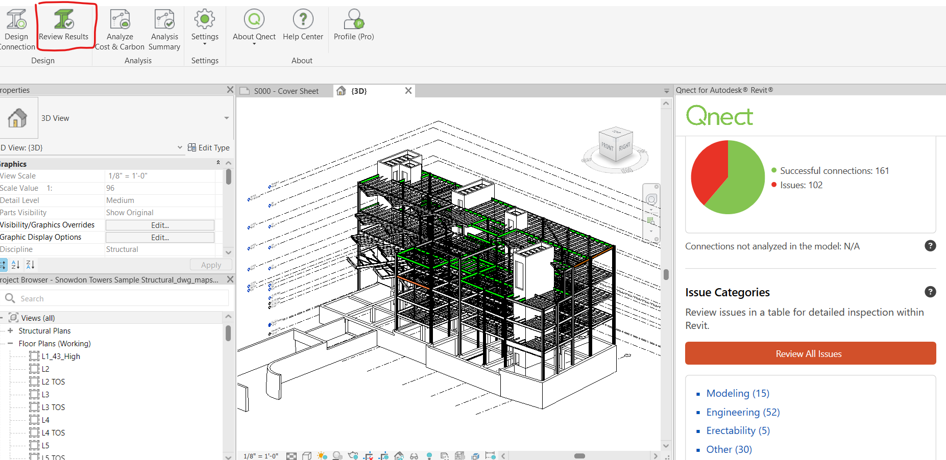
After the user performs analyses they can come back later to review the results. By selecting Review Results, the user can get a holistic view of issues and designed connections for the model. Note the dashboard count is for the entire model.
Viewing results within the model can be done in these ways
- By unselecting all objects in the model, the user can view all model results at once. This includes data from multiple analysis runs.
- To view for just a level or selected elements, go to a floor plan and select the beams and columns and select Review.
- Select at least two joining members
Review All Issues - This brings up a list view of issues and their descriptions. Users can select a row and it highlights the location in the model.
Review Successful Connections - Review all successful connections in the model to see which ones connect. Turn on other column fields to see the connection codes, design forces used, utility factors.
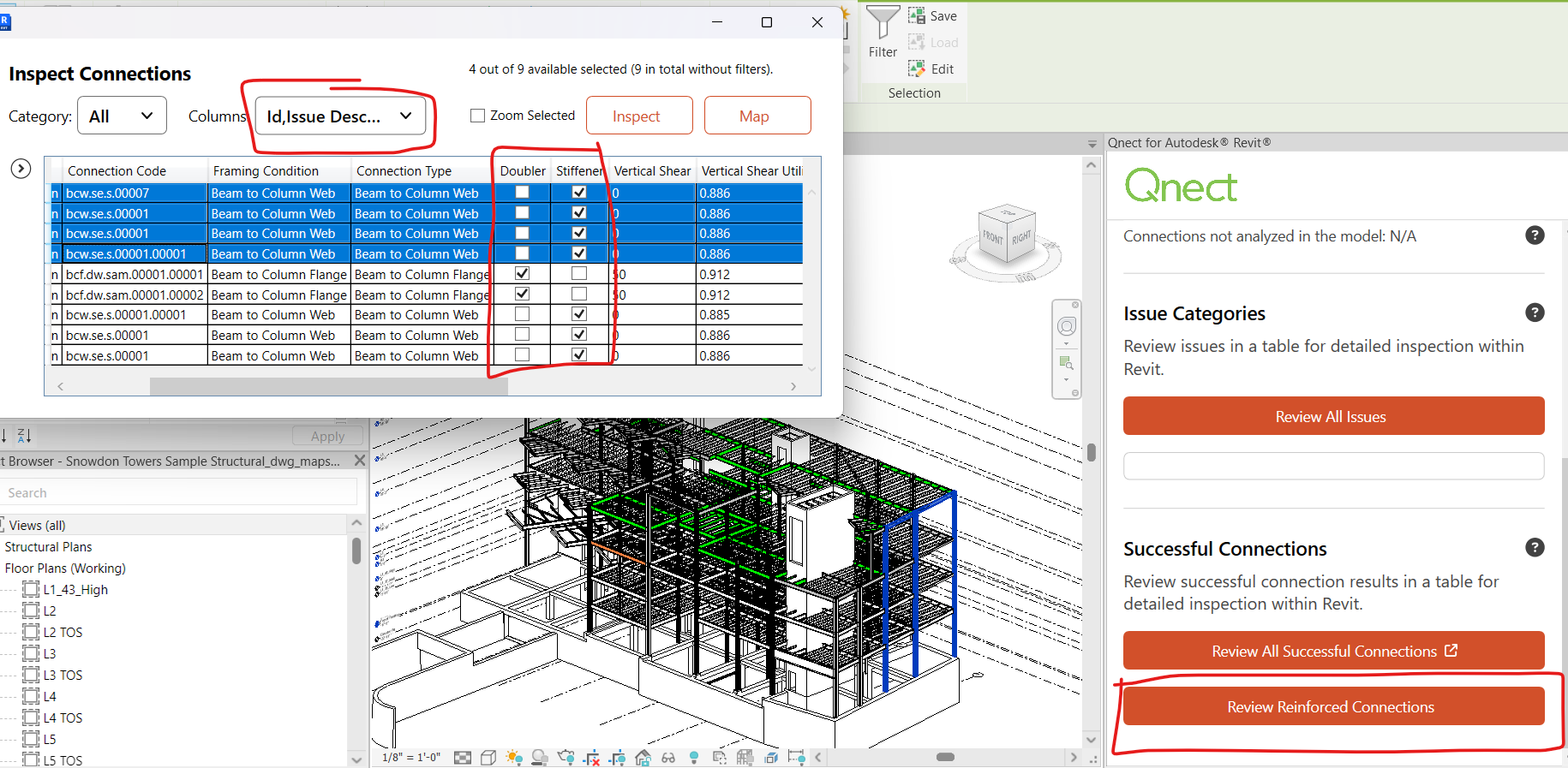
Review Reinforced Connections - lists out designed connections that require column stiffeners or web doublers, beam doublers, support stabilizer plates for columns or girders.
Issue Categories
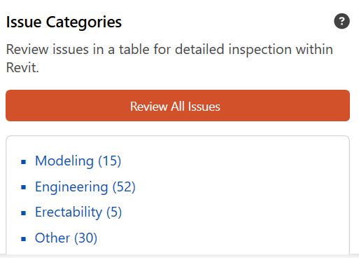
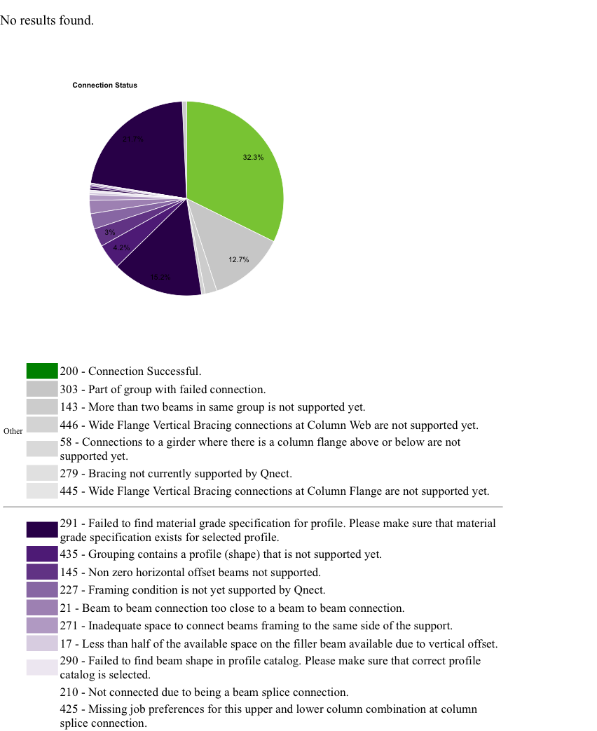
The Review All Issues lists issues by 5 Issue Categories.
- Modeling - issues related to modeling workpoints, material grades and other non-engineering issues. These are best addressed by the BIM modeler or technician. They should be worked on first because solving them may lead to other issues in the categories below.
- Engineering - These relate to local limit state checks of the framing that need to be addressed
- Connection Design - Mostly related to settings in the Preferences that limit the ability to complete the connection design. Some expertise in connection design is needed to revise these settings.
- Constructability - Fit up issues like welding or bolting access issues, beams to close together to be swung in by a crane etc.
- Other - these are issues where Qnect just doesn’t include this scope. Also the issues for neighboring connections that won’t connect due to a neighboring connection issue. Once the neighboring issues are resolved these ones will automatically be resolved unless they have their own specific issues.
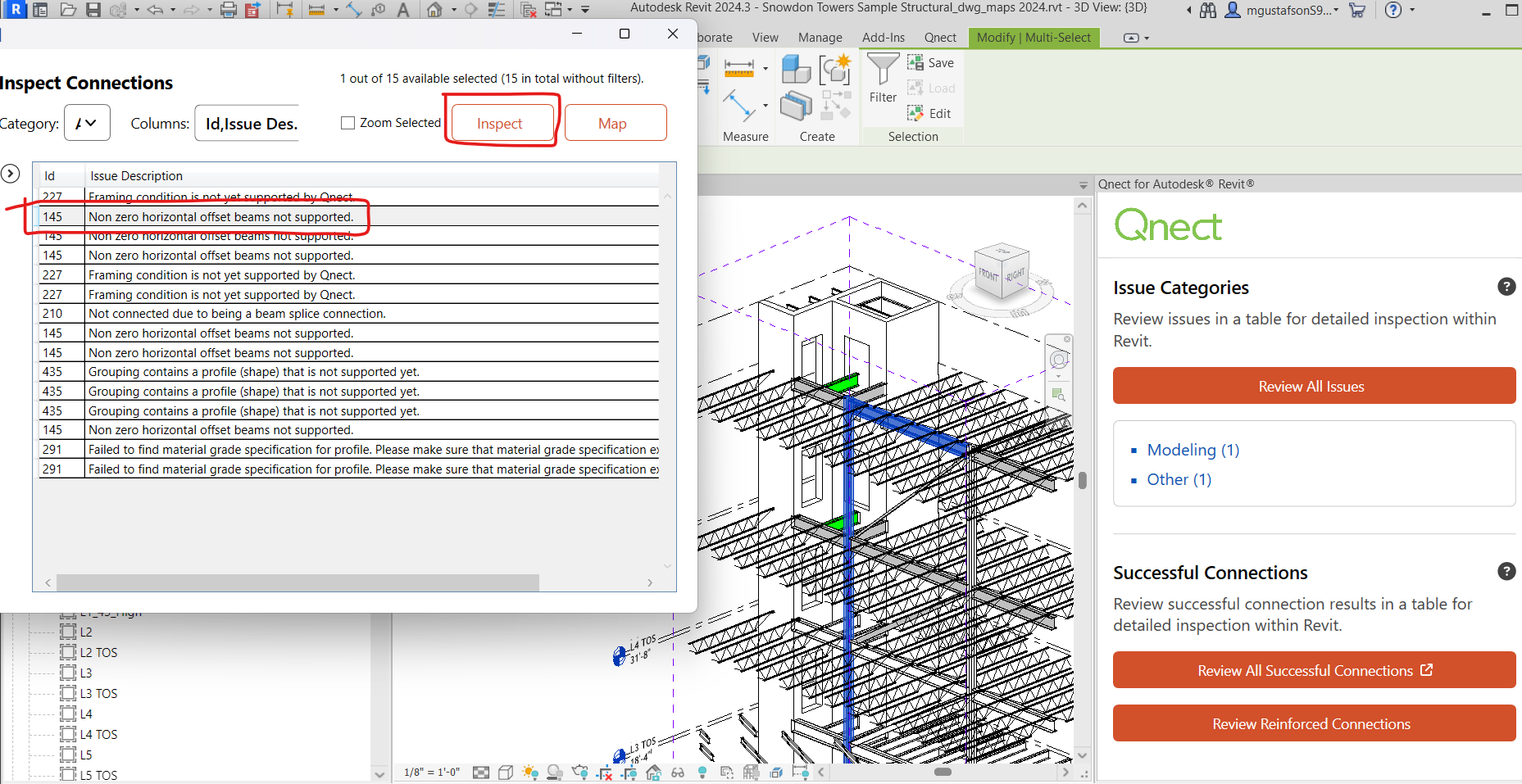
- Click the Modeling link to get a Inspect Connections view list of all the Modeling Issues in the model.
- Select a line item and select Inspect. This will take you to the particular issue.
- Go to the Columns header to turn on other fields like Resolutions.
 Every time a user does an analysis, they receive an email with a NoConnect Summary. This link includes issue counts and Issue Categories in a pie chart. This is another way to track progress of your issues over time.
Resolutions
Users will want to decide how to resolve the issues once identified, taking action right away in the Revit model or discussing with other team members. Qnect provides a Resolution in the interface. Otherwise see Help Support section for Qnect’s Q AI bot which provides further insights into resolving issues.
 Structural teams can delegate Modeling Issues to the BIM team to have them address right away. Then rerun the model so only Engineering, Connection Design and Erectability issues remain for the structural engineers to resolve.
This will help guide who best to coordinate with to resolve the particular issue. For example, if the BIM modeler is running the analysis, they can resolve the Modeler Check items themselves and then coordinate the others with the engineering teams.
Better explanations for what the Issue Descriptions means as well as suggested strategies to resolve them are described in the Top Issues and Resolutions documentation
Review Reinforced Connections
Users can visualize what successful connections still require reinforcement of beam webs for gravity beam connections (i.e, web doublers) and reinforcement of columns for moment connections (column stiffeners and doubler plates). The Inspect Connection list can show which joints require what particular joint reinforcement. Turn on the column fields for Secondary Doublers (for beams), Main Doubler (column doubler plates) and Stiffeners (column stiffeners) by activating the columns.
Select Beam Parameters
To access individual calculations or issue reports,
- select a beam.
- Go to End 1 (Start) or End 2 (End) tab.
- Then open Connection Report.
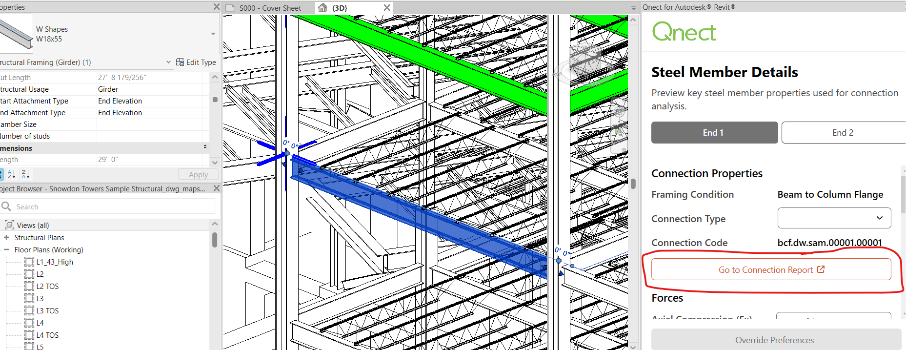
To see the beam end highlight in the model, go to the view’s V/G Overrides > Visibility / Graphic Overrides, check the box for Lines.
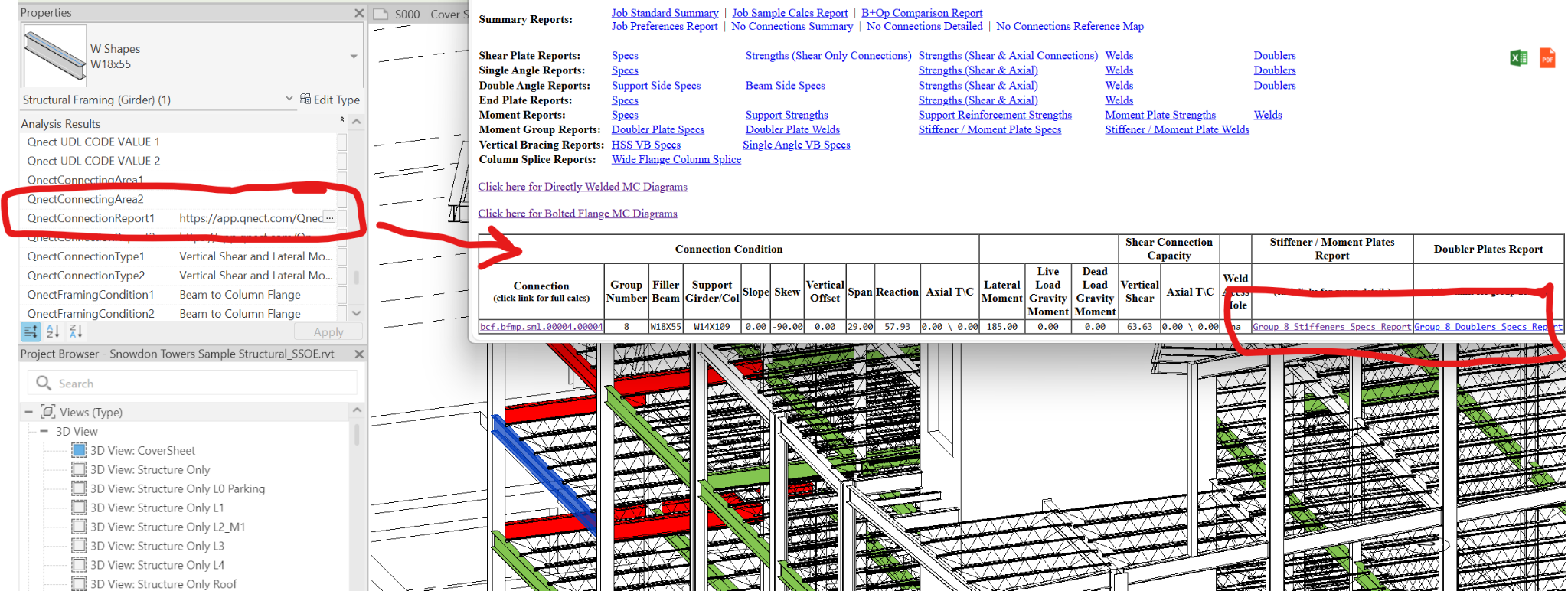
Also, the connection design reports are hyperlinked into the beam parameters provide details of the doublers and stiffeners for a particular connection.
At the beam level, users can edit the design forces
- Select End 1
- Go to Shear major axis Fy.
- Change value
- Update Preferences
Now values update in Revit parameters
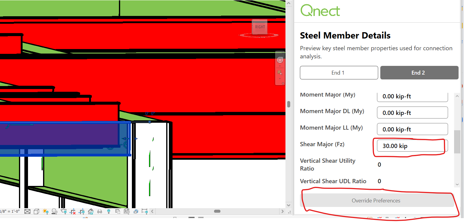
Users can also override at the joint level
- Connection types (13 options)
- Continuously braced top flange
Inspect Connection - A Deeper Dive
- Select issues in the Inspect Connections view list so they highlight in the model. Selecting one issue will highlight both the primary and secondary elements.
- Zoom to selected - zooms into the selected elements within the model. It does not filter out or clip away elements around it.
- Inspect: This button adds clip planes into the model around the selected elements. This feature can be used in combination with Zoom to Selected.
- Map: Creates a 2D drawing map using existing structural plan templates. Here the Issues are annotated at the beam ends of the plans.
Create drawing maps
- User can load existing Floor Plan drawing templates to then annotate Issue ID and Description information on to.
- It is best to copy an existing floor plan template and customize it for what you want to include on it. This includes hiding any reference models or other information not needed on this coordination drawing.
- The purpose of the drawing map is to share with engineers not using Revit who want to review the issues and take action upon them in their structural analysis tools or make markups on 2D pdfs.
Visualize 3D Connections
3D connection information can be viewed in a stand alone viewer and in the Revit model as an IFC reference link. The connections need to be first designed successfully. Once they have a calculation report they are ready to view.
- Turn on the Structural Connections in the view filters so that the generic connection objects are visible.
- Select on the generic object. Note that there may be more than one at a joint. You know which one to select based on the two directions the handles display.
- Open 3D Viewer. You will get a pop up of the viewer. It includes the framing and connection material.
- Load IFC Connection. This will insert the IFC in the model. It includes the connection material and the fabricated framing material. Note that the user is prompted to Add Parameters. This is part of what Revit needs to do in order to load the IFC file. Add Parameters. Then the model will insert.
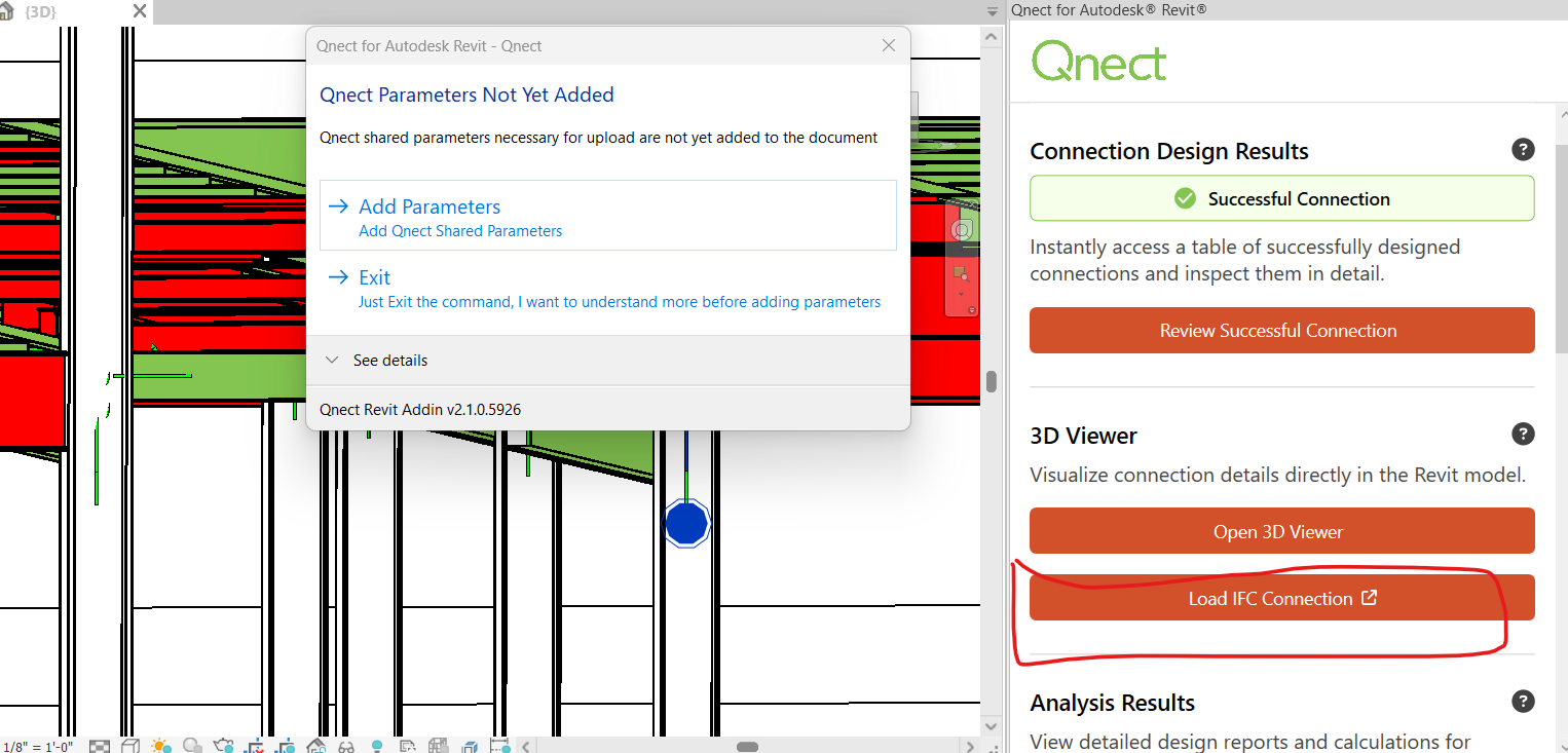
Users can show the IFC in their background drawings, annotate to them, add elevations, clash check on Autodesk Construction Cloud if reference models are pushed to the cloud.
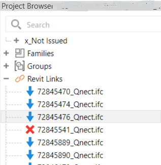
To remove IFC files, users can go to the Manage Links ribbon or in the left pane Project Browser to unload files. Also users can go to Settings > Project Settings > Remove Model Data and check the IFC model check box.